MainStage User Guide
- Welcome
-
- Overview of Edit mode
-
- Select patches and sets in the Patch List
- Copy, paste, and delete patches
- Reorder and move patches in the Patch List
- Add and rename patches
- Create a patch from several patches
-
- Overview of the Patch Settings Inspector
- Select patch settings in the Patch Library
- Set the time signature for patches
- Change the tempo when you select a patch
- Set program change and bank numbers
- Defer patch changes
- Instantly silence the previous patch
- Change patch icons
- Transpose the pitch of incoming notes for a patch
- Change the tuning for a patch
- Add text notes to a patch
-
- Overview of channel strips
- Add a channel strip
- Change a channel strip setting
- Configure channel strip components
- Show signal flow channel strips
- Hide the metronome channel strip
- Create an alias of a channel strip
- Add a patch bus
- Set channel strip pan or balance positions
- Set channel strip volume levels
- Mute and solo channel strips
- Use multiple instrument outputs
- Use external MIDI instruments
- Reorganize channel strips
- Delete channel strips
-
- Overview of the Channel Strip Inspector
- Choose channel strip settings
- Rename channel strips
- Change channel strip colors
- Change channel strip icons
- Use feedback protection with channel strips
- Set keyboard input for a software instrument channel strip
- Transpose individual software instruments
- Filter MIDI messages
- Scale channel strip velocity
- Set channel strips to ignore Hermode tuning
- Override concert- and set-level key ranges
- Add text notes to a channel strip in the Channel Strip Inspector
- Route audio via send effects
-
- Screen Control Inspector overview
- Replace parameter labels
- Choose custom colors for screen controls
- Change background or grouped screen control appearance
- Set screen controls to show the hardware value
- Set parameter change behavior for screen controls
- Set hardware matching behavior for screen controls
- Reset and compare changes to a patch
- Override concert- and set-level mappings
-
- Overview of mapping screen controls
- Map to channel strip and plug-in parameters
- Map screen controls to actions
- Map a screen control to multiple parameters
- Use screen controls to display PDF document pages
- Edit the saved value for a mapped parameter
- Set drum pads or buttons to use note velocity
- Map screen controls to all channel strips in a patch
- Undo screen control parameter mappings
- Remove screen control mappings
- Work with graphs
- Create controller transforms
- Share patches and sets between concerts
- Record the audio output of a concert
-
- Overview of concerts
- Create a concert
- Open and close concerts
- Save concerts
- How saving affects parameter values
- Clean up concerts
- Consolidate assets in a concert
- Rename the current concert
-
- Overview of the Concert Settings Inspector
- Set MIDI Routing to channel strips
- Transpose incoming note pitch for a concert
- Define the program change message source
- Send unused program changes to channel strips
- Set the time signature for a concert
- Change the tuning for a concert
- Set the pan law for a concert
- Add text notes to a concert
- Control the metronome
- Silence MIDI notes
- Mute audio output
-
- Layout mode overview
-
- Screen control parameter editing overview
- Lift and stamp screen control parameters
- Reset screen control parameters
- Common screen control parameters
- Keyboard screen control parameters
- MIDI activity screen control parameters
- Drum pad screen control parameters
- Waveform screen control parameters
- Selector screen control parameters
- Text screen control parameters
- Background screen control parameters
- How MainStage passes through MIDI messages
- Export and import layouts
- Change the aspect ratio of a layout
-
- Before performing live
- Use Perform mode
- Screen controls in performance
- Tempo changes during performance
- Tips for performing with keyboard controllers
- Tips for performing with guitars and other instruments
- Tune guitars and other instruments with the Tuner
- The Playback plug-in in performance
- Record your performances
- After the performance
- Tips for complex hardware setups
-
- Overview of keyboard shortcuts and command sets
-
- Concerts and layouts keyboard shortcuts
- Patches and sets (Edit mode) keyboard shortcuts
- Editing keyboard shortcuts
- Actions keyboard shortcuts
- Parameter mapping (Edit mode) keyboard shortcuts
- Channel strips (Edit mode) keyboard shortcuts
- Screen controls (Layout mode) keyboard shortcuts
- Perform in Full Screen keyboard shortcuts
- Window and view keyboard shortcuts
- Help and support keyboard shortcuts
-
-
- Use MIDI plug-ins
-
- Arpeggiator overview
- Arpeggiator control parameters
- Note order parameters overview
- Note order variations
- Note order inversions
- Arpeggiator pattern parameters overview
- Use Live mode
- Use Grid mode
- Arpeggiator options parameters
- Arpeggiator keyboard parameters
- Use keyboard parameters
- Assign controllers
- Modifier controls
- Note Repeater controls
- Randomizer controls
-
- Use Scripter
- Use the Script Editor
- Scripter API overview
- MIDI processing functions overview
- HandleMIDI function
- ProcessMIDI function
- GetParameter function
- SetParameter function
- ParameterChanged function
- Reset function
- JavaScript objects overview
- Use the JavaScript Event object
- Use the JavaScript TimingInfo object
- Use the Trace object
- Use the MIDI event beatPos property
- Use the JavaScript MIDI object
- Create Scripter controls
- Transposer controls
-
-
- Alchemy overview
- Alchemy interface overview
- Alchemy Name bar
- Alchemy file locations
-
- Alchemy source overview
- Source master controls
- Import browser
- Source subpage controls
- Source filter controls
- Source filter use tips
- Source elements overview
- Additive element controls
- Additive element effects
- Spectral element controls
- Spectral element effects
- Pitch correction controls
- Formant filter controls
- Granular element controls
- Sampler element controls
- VA element controls
- Wide unison mode
- Source modulations
- Morph controls
- Alchemy master voice section
- Alchemy Extended parameters
-
- Playback plug-in overview
- Add a Playback plug-in
- Playback interface
- Use the Playback waveform display
- Playback transport and function buttons
- Playback information display
- Playback Sync, Snap To, and Play From parameters
- Use the Playback group functions
- Use the Playback Action menu and File field
- Use markers with the Playback plug-in
-
- Sample Alchemy overview
- Interface overview
- Add source material
- Edit mode
- Play modes
- Source overview
- Synthesis modes
- Granular controls
- Additive effects
- Additive effect controls
- Spectral effect
- Spectral effect controls
- Filter module
- Lowpass, bandpass, and highpass filters
- Comb PM filter
- Downsampler filter
- FM filter
- Envelope generators
- Mod Matrix
- Modulation routing
- Motion mode
- Trim mode
- More menu
-
- Sculpture overview
- Sculpture interface
- Global parameters
- Amplitude envelope parameters
- Use the Waveshaper
- Filter parameters
- Output parameters
- Define MIDI controllers
- Extended parameters
-
- Studio Piano
- Copyright and trademarks
Sampler Synth pane in MainStage
You can use the Synth parameters to control Sampler global and filter settings for the entire loaded sampler instrument. Click the Details button at the top right of the Synth pane to view or hide the Synth Details slide-out pane which provides additional parameters. Several synthesizer parameter handling commands are also found in the Navigation bar pop-up menu. See Sampler overview.
If you’re new to the concepts and use of synthesizers, see Synthesizer basics overview.
You can use the Modulators pane to assign and adjust the LFOs and envelopes which control synthesizer and other parameters and can use the Mod Matrix pane to set up modulation routings. See Sampler modulation overview.
You can adjust and control individual samples (zones), or grouped samples, in the Mapping and Zone panes. See Sampler Mapping and Zone pane overview.
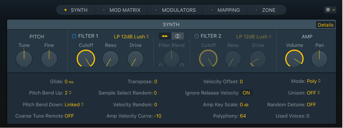
Synth pane parameters
Double-click a parameter knob to reset it to the default value.
Double-click a parameter value field to enter in a new value. Press Return to complete the operation.
Details button: View or hide a slide-out pane which provides additional synthesis parameters. See Sampler Synth Details.
Tune knob and field: Raise or lower the pitch of the sampler instrument in semitone increments. At the default (zero) position, no pitch change occurs.
Fine knob and field: Tune the sampler instrument in cent increments—1/100 of a semitone. Use this parameter to correct samples that are slightly out of tune.
Filter On/Off buttons: Turn each filter section on or off. Each filter can have an independent or shared envelope, defined in the Mod Matrix pane. Turning off the filter section makes it easier to hear adjustments to other sound parameters because the filter always heavily affects the sound.
Filter Type pop-up menu: Choose the type and slope of the filter. See Sampler filter types.
Cutoff knob: Set the cutoff frequency of the filter. The Cutoff value also serves as the starting point for any modulation involving the filter.
In a lowpass filter, the higher the cutoff frequency is set, the higher the frequencies of signals that are allowed to pass.
In a highpass filter, the cutoff frequency determines the point where lower frequencies are suppressed, with only upper frequencies allowed to pass.
In a bandpass/band-rejection filter, the cutoff frequency determines the center frequency for the bandpass or band-rejection filter.
Resonance knob: Boost or cut the frequency area surrounding the cutoff frequency. Very high Resonance values introduce self-oscillation, causing the filter to produce an audible sine wave.
In a lowpass filter, resonance emphasizes the frequencies at the cutoff frequency.
In a highpass filter, resonance emphasizes the frequencies at the cutoff frequency.
In bandpass filters, resonance emphasizes the portions of the signal—the frequency band—that surround the defined frequency, set with the Cutoff knob. In Sampler, Resonance defines the width of the frequency band.
Drive knob: Overdrive the filter input, leading to a denser, more saturated signal, which introduces additional harmonics. Drive affects each voice independently. When every voice is overdriven individually—like having six fuzz boxes for a guitar, one for each string—you can play extremely complex harmonies over the entire keyboard range. They’ll sound clean, without unwanted intermodulation effects spoiling the sound. Some Drive settings lead to a different tonal character. The way analog filters behave when overdriven forms an essential part of the sonic character of a synthesizer. Each synthesizer is unique in the way its filters behave when overdriven. Sampler is flexible in this regard, allowing tonal colors that range from a subtle fuzz to a hard distortion.
Filter configuration buttons: Switch between a series or parallel filter configuration.
Series button: Turn on to pass the signal through the first filter, which forwards this filtered signal through Filter 2. The output signal of Filter 2 is then sent to the input of the dynamic stage (Amplifier section).
Parallel button: Turn on to pass the signal through both filters. If the Filter Blend knob is set to the center position, you’ll hear a 50/50 mix of the signal, routed via Filter 1 and Filter 2. The output signals of the two filters are mixed, then sent to the input of the dynamic stage (Amplifier section).
Tip: If one of the two filters is turned off (bypassed), you can mix the original signal and the filtered signal to create a simple phaser effect, for example.
Filter Blend knob: Set the balance between Filter 1 and Filter 2 in parallel mode. See Crossfade between Sampler filters.
Volume knob: Set the overall output signal level of Sampler. The levels of individual samples or groups of samples are set in the Mapping and Zone panes.
Pan knob: Set the pan position—or balance—of the Sampler output signal.
Create or view a modulation routing with the Synth pane shortcut menu
In MainStage Sampler, Control-click on any parameter in the Synth pane that is available as a modulation target to open a shortcut menu, then choose one of the following:
Add Modulation: Use to create a new modulation routing in the Mod Matrix pane and choose the Source parameter from the pop-up menu.
Show Modulation: Use to highlight all existing modulation routings that use the parameter by activating the view filter in the Mod Matrix pane. See Use the Sampler Mod Matrix.