Two discrete signal busses—Bus A and Bus B—provide flexibility when you’re setting up signal processing chains. Bus A (lower) and Bus B (upper) appear as horizontal gray lines in the Router. Stompboxes that you drag into the Pedal area are inserted into Bus A by default. Click the stompbox label to create Bus B if not shown, or to move the pedal between Bus A and Bus B.
Pedalboard can be inserted as a mono, mono-to-stereo, or stereo instance. This affects the appearance of the Router busses, and also available options.
In mono instances: A single gray line appears between elements on each active Bus.
In mono-to-stereo instances: One or two parallel gray lines appear between elements on each active Bus, depending on whether switchable mono or stereo stompboxes are inserted. See the task in this section.
In stereo instances: Two parallel gray lines appear between elements on each active Bus.
The Router is shown only when a stompbox is added to the Pedal area. Once a stompbox has been added, the Router appears when you move your pointer to a position immediately above the Pedal area, and it disappears when you move the pointer away. When you create a second bus routing, the Router remains open even when your pointer is not over it.
Notes on Splitter utility and Mixer utility use
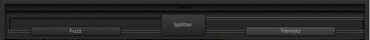
Dragging a Splitter utility into the Pedal area automatically inserts a Mixer utility to the far right of all inserted pedals.
You cannot drag a Splitter utility to the far right of all inserted pedals, to directly after an inserted Splitter utility, to directly in front of an inserted Mixer utility, or to an empty space in the Pedal area.
Dragging a Mixer utility into the Pedal area automatically creates a split point at the earliest possible point—the leftmost point—within the signal chain.
You cannot drag a Mixer utility to the first slot in the Pedal area, to between an inserted Splitter and Mixer utility combination, or directly to the right of an inserted Mixer utility.
In MainStage, do one of the following:
Move your pointer immediately above the Pedal area to open the Router, and click the name of a stompbox in the Router.
Two gray lines (or two sets of parallel gray lines in a stereo instance) appear in the Router. The lower line represents the Bus A routing and the upper line, the Bus B routing. The pedal name moves to the upper line. The chosen stompbox is now routed to Bus B, and a Mixer utility pedal is automatically added to the end of the signal chain.
Drag a Splitter utility pedal into the Pedal area when more than one pedal is inserted.
This also inserts a Mixer at the end of the signal chain if one doesn’t already exist.
In MainStage, do one of the following:
Delete the Mixer and Splitter utility pedals from the Pedal area.
Remove all stompboxes from the Pedal area. This automatically removes any Mixer utility.
In MainStage, click the name of the pedal in the Router. (You can also click the lower gray line immediately above the pedal to remove the pedal from the second bus.)
Note: The removal of all effects from Bus B does not remove the second bus. The Mixer utility pedal remains in the Pedal area, even when a single stompbox (effect) is in the Pedal area. This enables parallel routing of wet and dry signals. Only when all pedal effects are removed from the Pedal area are the Mixer utility and second bus removed.
When more than one bus is active, a number of dots appear along the “cables”—the gray lines—in the Router. These represent the output of the pedal to the lower left of the dot.
In MainStage, click the appropriate dot to determine the split point where the signal is routed between busses.
A cable appears between the busses when you click a dot.
Note: You cannot create a split point directly before or after the Mixer utility.
Split marker: Click to move an existing Splitter utility. Double-click to replace a bus split point with a Splitter utility.
The Splitter utility appears in the Pedal area.
Bus split point marker: Indicates a routing between buses. Double-click a Splitter label to remove the utility from the Pedal area and replace it with a bus split point marker.
In MainStage, drag the Mixer utility to a new position, either to the left or to the right.
If you move the Mixer utility to the left, the “downmix” of Bus A and Bus B occurs at the earlier insertion point. Relevant effect pedals are moved to the right and are inserted into Bus A.
If you move the Mixer utility to the right, the “downmix” of Bus A and Bus B occurs at the later insertion point. Relevant effect pedals are moved to the left and are inserted into Bus A.
Note: A Mixer pedal cannot be moved to a position directly following or preceding a corresponding split point or Splitter utility.
In MainStage, drag the Splitter utility to a new position, either to the left or to the right.
If you move the Splitter utility to the left, the split between Bus A and Bus B occurs at the earlier insertion point. Relevant effect pedals are moved to the right and are inserted into Bus A.
If you move the Splitter utility to the right, the split between Bus A and Bus B occurs at the later insertion point. Relevant effect pedals are moved to the left and are inserted into Bus A.
Note: A Splitter pedal cannot be moved to a position directly preceding (or to the right of) a corresponding Mixer utility.
When Pedalboard is inserted as a mono-to-stereo plug-in, modulation effects and the Mixer utility can be used to switch between stereo or mono routings.
In MainStage, click the icon at the right of the element name on Bus A or Bus B to switch between mono or stereo mode.
Single circle: Indicates a mono stompbox or Mixer utility. Signals beyond this point on the respective bus are mono, shown as a single gray line.
The mono signal path on Bus A or Bus B is maintained until a modulation or Mixer stompbox is inserted, and is switched to stereo mode. Signals beyond this point on the respective bus will be stereo. This is indicated by a double gray line.
Linked circles: Indicates a stereo stompbox or Mixer utility. Signals beyond this point on the respective bus are stereo, shown as a double gray line.
The stereo signal path on Bus A or Bus B is maintained until a modulation or Mixer stompbox is inserted, and is switched to mono mode. Signals beyond this point on the respective bus will be mono. This is indicated by a single gray line.