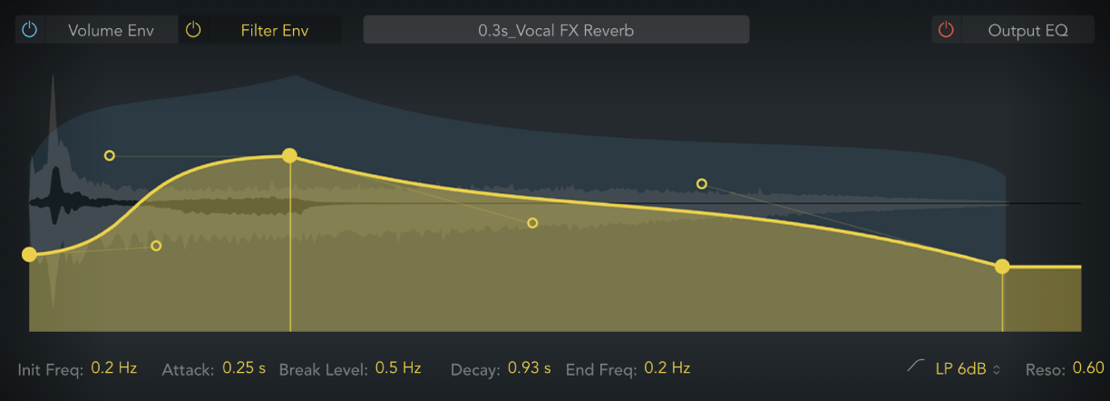
Space Designer filter and envelope controls in Final Cut Pro for Mac
The filter provides control over the timbre of the reverb.
You can choose from several filter types and also have envelope control over filter cutoff. Changes to filter settings result in a recalculation of the impulse response rather than a direct change to the sound as it plays through Space Designer.
The main filter parameters are shown at the right side of the parameter bar when the filter envelope is selected in the main display.
Click the Filter Env On/Off button to enable the filter envelope and the filter itself. You can use the envelope to control the filter cutoff frequency over time. You can adjust all filter envelope parameters, either numerically in the parameter bar or graphically in the main display using the techniques discussed in Edit Space Designer envelopes in Final Cut Pro for Mac.
To add the Space Designer effect to a clip and show the effect’s controls, see Add Logic effects to clips in Final Cut Pro for Mac.

Main filter controls
Filter mode pop-up menu: Set the filter mode.
6 dB (LP): Bright, general-purpose lowpass filter mode that retains the top end of most material while still providing some filtering.
12 dB (LP): Warm, lowpass filter mode without drastic filter effects that is useful for smoothing bright reverbs.
BP: 6 dB per octave bandpass design that reduces the low and high ends of the signal, leaving the frequencies around the cutoff frequency intact.
HP: 12 dB per octave/two-pole highpass design that reduces the level of frequencies that fall below the cutoff frequency.
Resonance field: Emphasize frequencies above, around, or below the cutoff frequency. The impact of the resonance value on the sound is highly dependent on the chosen filter mode, with steeper filter slopes resulting in more pronounced tonal changes.
Filter envelope controls
Init Freq (Initial Frequency) node and field: Set the initial cutoff frequency of the filter envelope. Drag the node vertically.
Attack node and field: Determine the time required to reach the Break Level. Drag the node horizontally.
Break Level node and field: Set the maximum filter cutoff frequency. This value also defines the separation point between the attack and decay phases of the overall filter envelope. Drag the node vertically. In other words, when the set level is reached after the attack phase, the decay phase begins. You can create interesting filter sweeps by setting the Break Level value lower than the Init Level parameter value.
Decay node and field: Determine the time required after the Break Level point to reach the End Freq value. Drag the node horizontally.
End Freq (Frequency) node and field: Set the cutoff frequency at the end of the filter envelope decay phase. Drag the node vertically.
Bezier curve node: Drag to create or change convex, concave, or S-curve shapes for the associated envelope phase.
Download this guide: Apple Books | PDF