MacBook Pro (14-inch and 16-inch, Nov 2023) Bottom Case
Before You Begin
 Warning
Read Battery Safety and follow workspace and battery handling guidelines before you begin.
Tools
Adjustable torque driver (10–34 Ncm) (923-02995)
Battery cover for 14-inch models (923-06086)
Battery cover for 16-inch models (923-06087)
Cut-resistant gloves (923-01368)
ESD-safe tweezers
Microterry polishing cloth
Nylon probe (black stick) (922-5065)
Pentalobe screwdriver (923-0731)
Permanent marker
Suction cup (922-8252)
Torque driver (blue, 0.65 kgf cm) (923-0448)
Torx Plus 3IP 44 mm half-moon bit (923-08468)
Torx Plus 5IP 50 mm bit (923-08673)
Refer to a full list of tools required for all repairs.
Removal
Note: If you’ve already completed the removal steps, skip to reassembly.
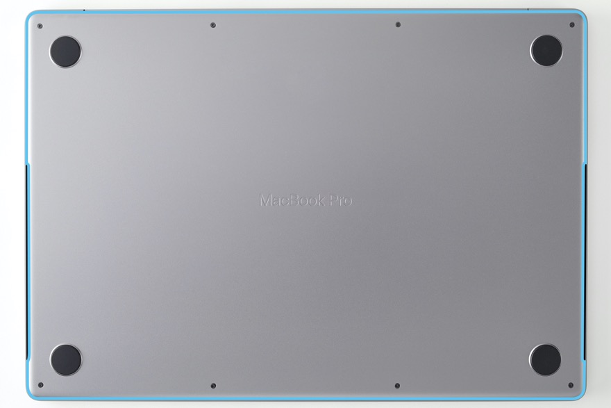
Place the computer on a clean, flat surface with the bottom faceup and the display hinge facing away from you.
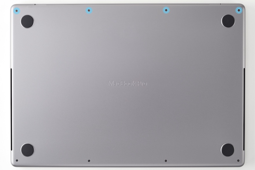
Use the pentalobe screwdriver to remove four long pentalobe screws.
Note: The screw color is matched to the computer finish.
MacBook Pro (14-inch, M3, Nov 2023)
silver (923-10122)
space gray (923-09792)
MacBook Pro (14-inch, M3 Pro or M3 Max, Nov 2023)
silver (923-06867)
space black (923-06869)
MacBook Pro (16-inch, Nov 2023)
silver (923-10061)
space black (923-10059)
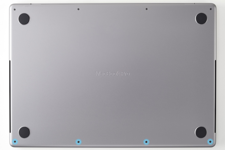
Use the pentalobe screwdriver to remove four short pentalobe screws.
Note: The screw color is matched to the computer finish.
MacBook Pro (14-inch, M3, Nov 2023)
silver (923-10123)
space gray (923-09793)
MacBook Pro (14-inch, M3 Pro or M3 Max, Nov 2023)
silver (923-06866)
space black (923-06868)
MacBook Pro (16-inch, Nov 2023)
silver (923-10060)
space black (923-10058)
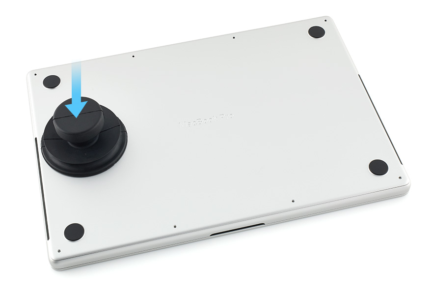
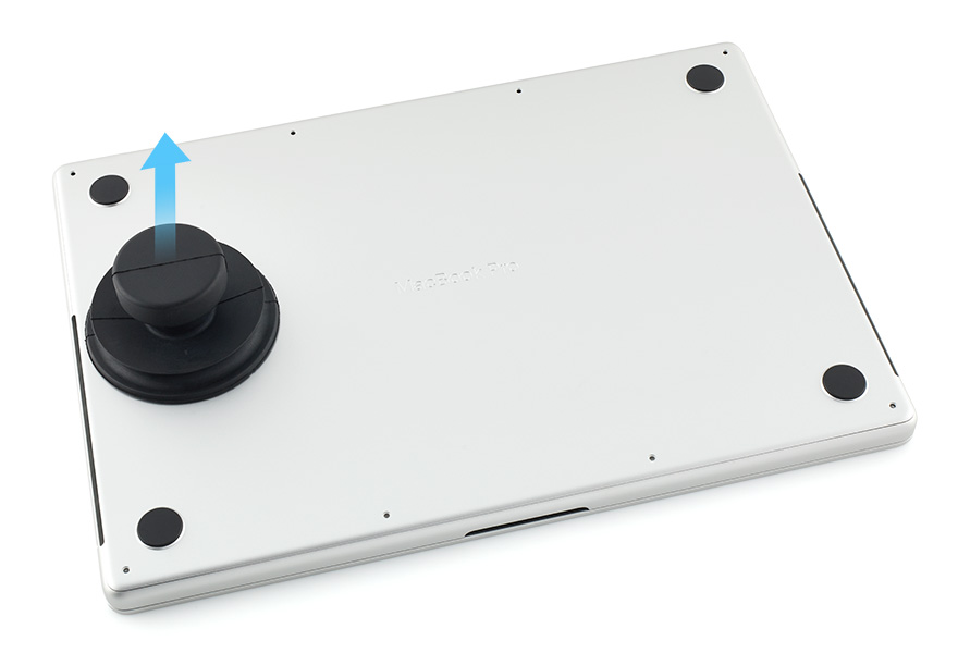
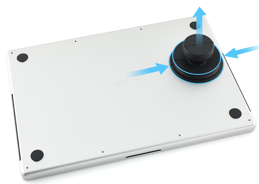
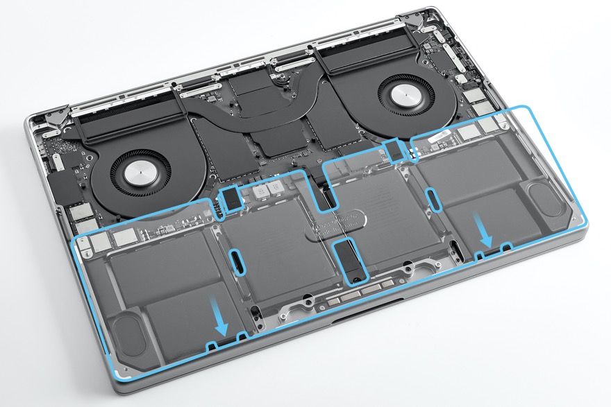
Four internal clips attach the bottom case to the top case. Press the suction cup to attach it to the left side of the bottom case.
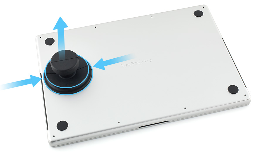
Pull up the handle of the suction cup until you feel the internal clip on the left release.
Squeeze the edges of the suction cup to release it.
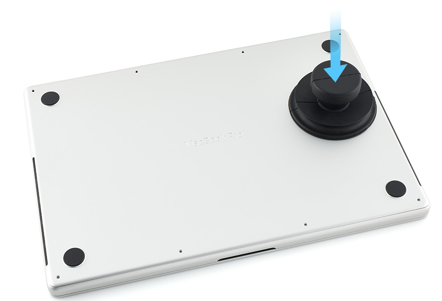
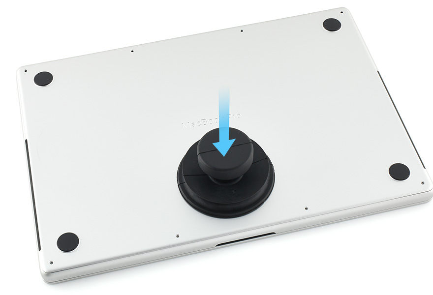
Move the suction cup to the right side and press the top to attach it to the bottom case.
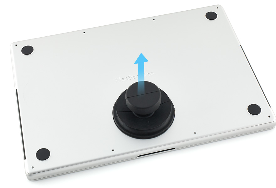
Pull up the handle of the suction cup until you feel the internal clip on the right release.
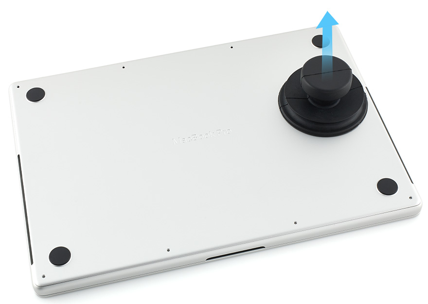
Squeeze the edges of the suction cup to release it.
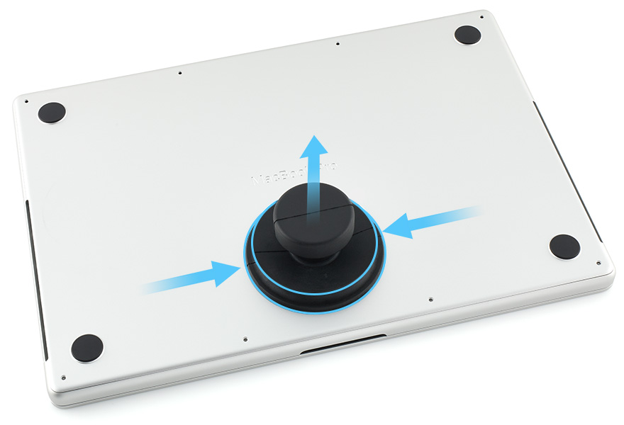
Move the suction cup to the lower middle and press the top to attach it to the bottom case.
Pull up the handle of the suction cup until you feel the two internal clips in the middle release.
Squeeze the edges of the suction cup to release it.
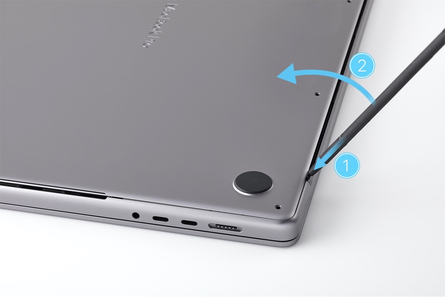
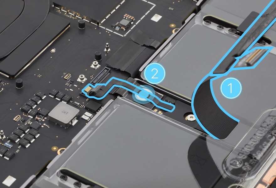
Insert the flat end of the black stick into the gap between the display and top case (1) as shown. Then pull the black stick to disengage the spring fingers (2). Repeat this on the other end of the gap.
Lift the bottom case off the top case and set it faceup on a clean, flat surface.
Important:
If you’re replacing the bottom case, keep the original bottom case until the repair is complete
Use a permanent marker to write the computer serial number on the inside of the replacement bottom case.
Note: If you're only replacing the bottom case, skip to reassembly step 9.
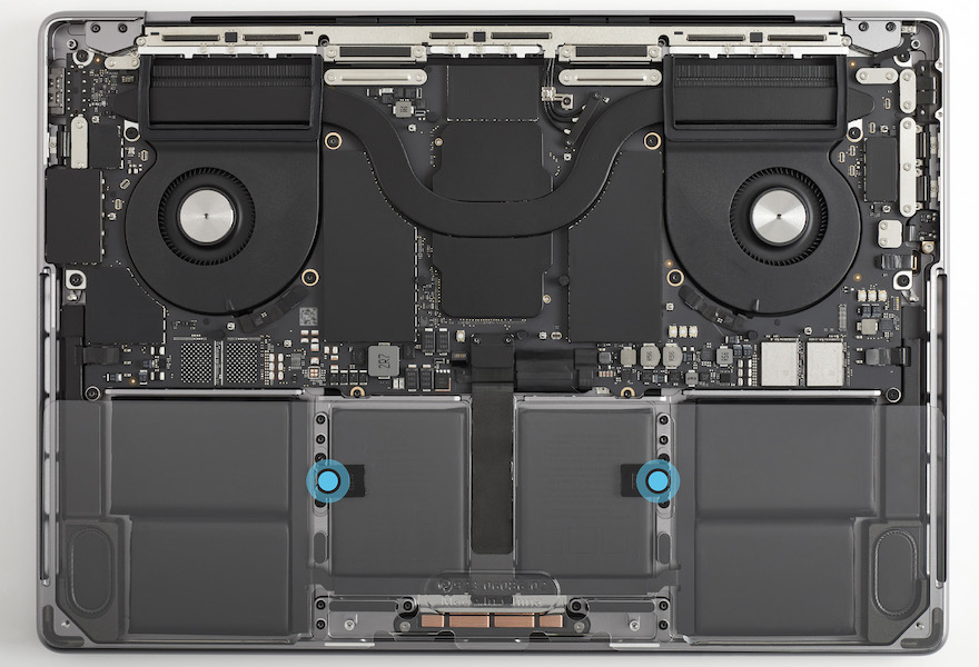
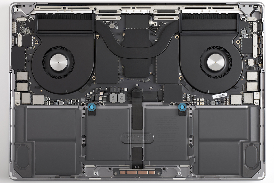
Place the battery cover on the battery.
Press the black tabs on the battery cover into the clips on the top case until you feel a click.
14-inch model
16-inch model
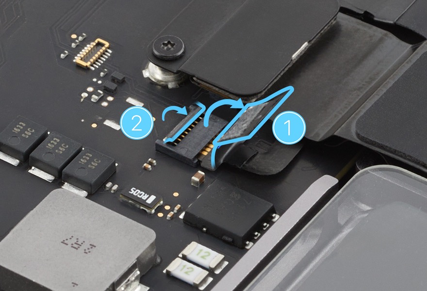
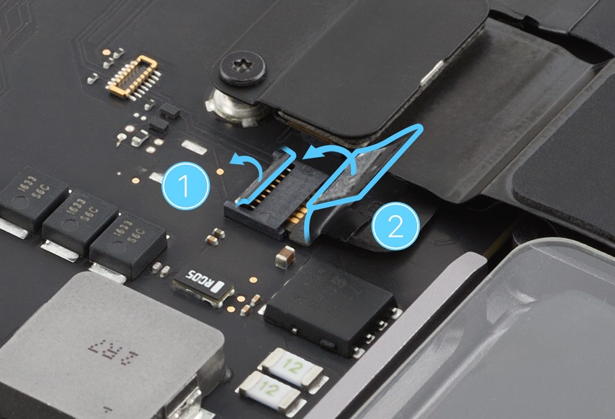
Gently peel the polyester film tab off the locking lever of the battery management unit (BMU) flex cable (1). Then use the black stick to flip up the locking lever (2).
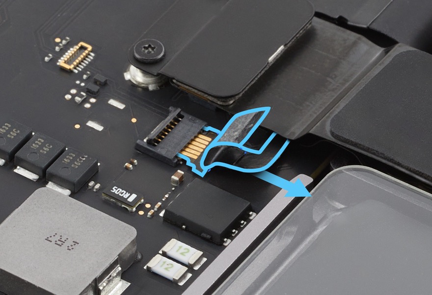
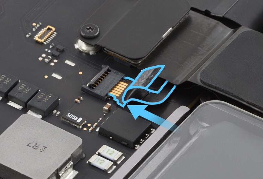
Slide the end of the BMU flex cable out of the connector.
 Caution: Wait one minute after disconnecting the BMU flex cable for the logic board to discharge. Then continue with the removal steps.
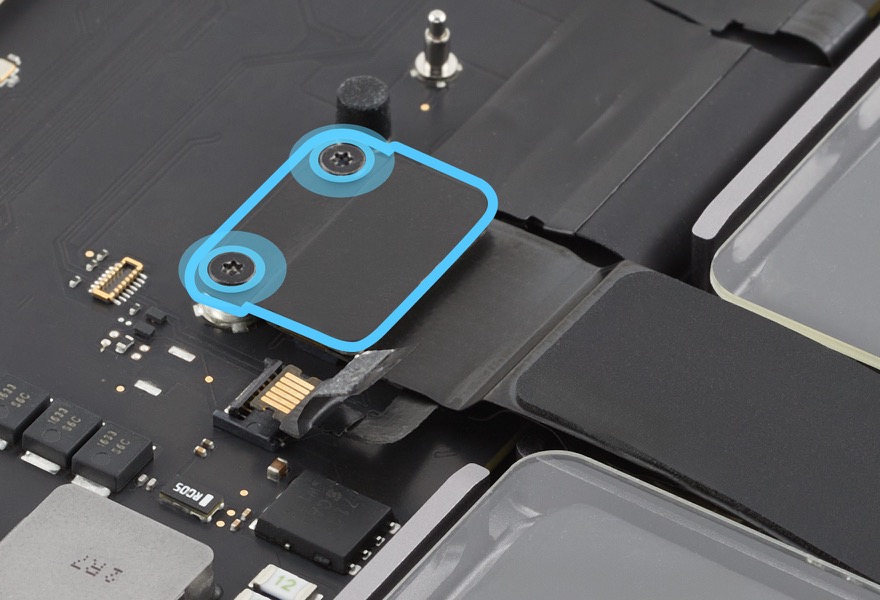
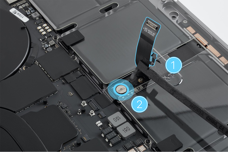
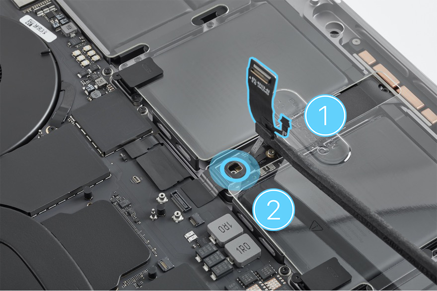
Use the blue torque driver and 3IP bit to remove the two 3IP screws (923-06851) from the trackpad connector cowling. Remove the cowling and save it for reassembly.
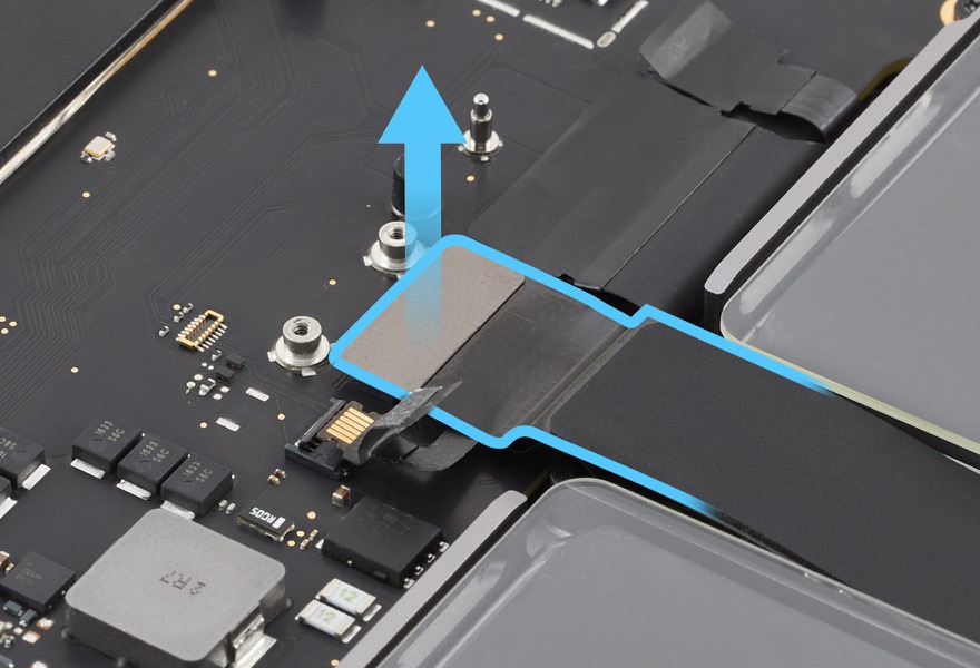
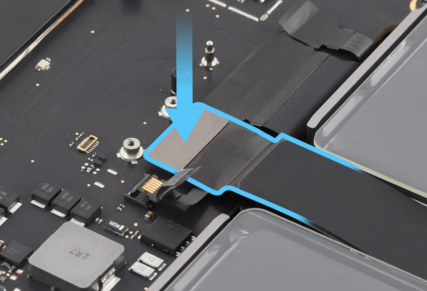
Lift the end of the trackpad flex cable off the connector on the logic board.
Gently fold back the trackpad flex cable (1). Then gently peel the BMU flex cable off the 5IP screw (923-06849) (2).
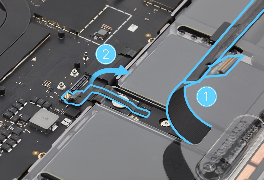
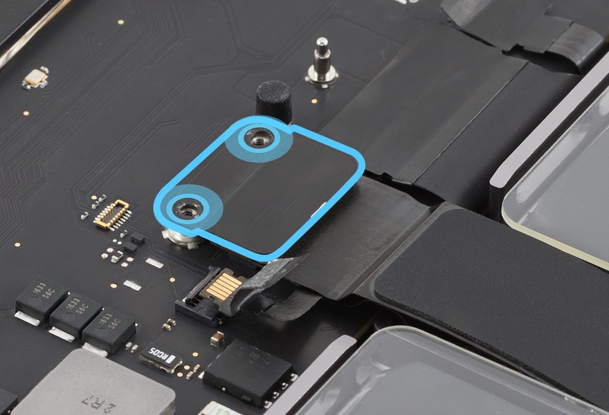
Use the black stick to hold back the flex cables (1). Then use the 10–34 Ncm adjustable torque driver and Torx Plus 5IP bit to remove the 5IP screw (2).
Reassembly
Important:
If you’re replacing the bottom case, keep the original bottom case until the repair is complete.
Use a permanent marker to write the computer serial number on the inside of the replacement bottom case.
Keep the 5IP bit in the 10–34 Ncm adjustable torque driver. Set the torque value to 19 Ncm.
Use the black stick to hold back the BMU and trackpad flex cables (1). Then use the adjustable torque driver and 5IP bit to reinstall the 5IP screw (923-06849) (2).
Use the black stick to hold back the trackpad flex cable (1). Then gently press the BMU flex cable (2) to adhere it to the 5IP screw.
Lay the trackpad flex cable flat. Then press the end of the trackpad flex cable to the connector on the logic board.
Important: If you installed a replacement trackpad flex cable, remove the adhesive backing. Then gently press to adhere the trackpad flex cable to the logic board.
Position the trackpad flex cable cowling over the end of the trackpad flex cable. Then use the blue torque driver and 3IP bit to reinstall the two 3IP screws (923-06851) into the cowling.
Slide the end of the BMU flex cable into the connector on the logic board.
Flip down the locking lever on the BMU flex cable connector (1). Then press the polyester film tab to the locking lever (2).
Hold the battery cover by the edges and lift it off the top case.
Use the microterry polishing cloth to ensure that the bottom case interior is clean and free of debris.
Position the bottom case over the top case. Align the back edge of the bottom case with the vent/antenna module. The long edge of the bottom case should be flush with the smooth plane of the vent/antenna module.
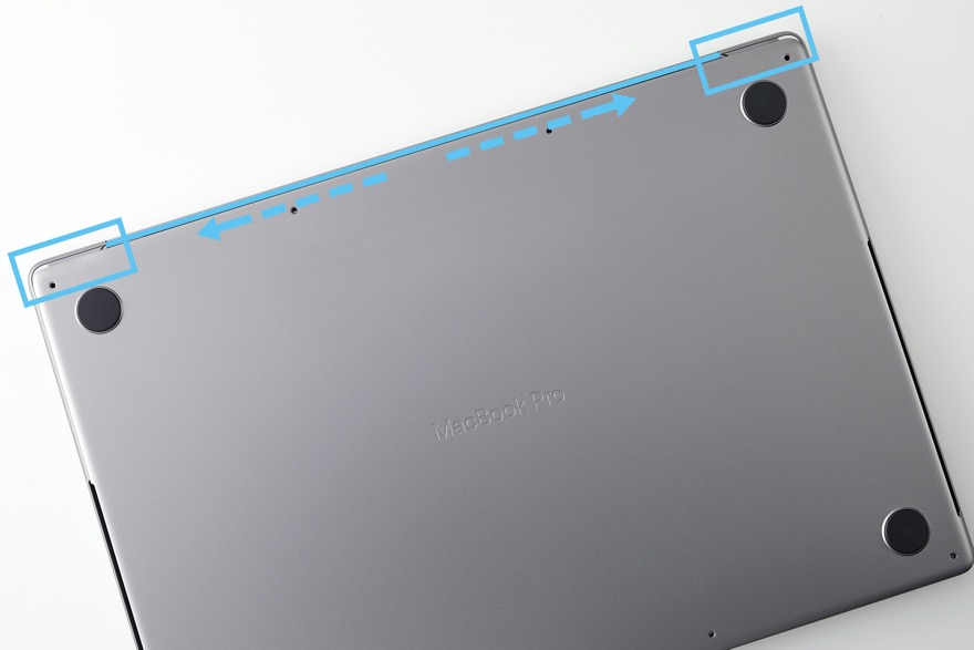
Put on the gloves. Hold the bottom case by the front corners and slowly push it away from you to align it with the display hinge and top case.

Feel the spring fingers lock as you push the bottom case.
Important: If the bottom case doesn’t align, pull it toward you to remove it. Then repeat steps 10 through 12.
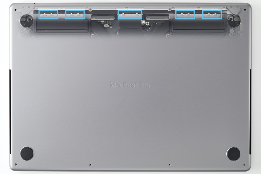
Lift the front edge of the bottom case no more than 1 inch (2.5 cm) to align the thermal fan ducts.
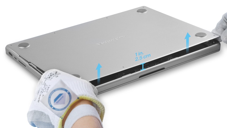
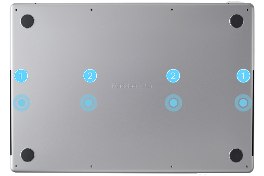
Press both sides of the bottom case simultaneously until you feel the two internal clips snap into place (1). Then simultaneously press the two areas in the middle (2) to attach the two remaining internal clips.
Ensure that all sides of the bottom case align with all sides of the top case. If the cases are misaligned, begin again at removal step 4.
Use the pentalobe screwdriver to reinstall the four long pentalobe screws.
Note: Use the correct screw color to match the computer finish.
MacBook Pro (14-inch, M3, Nov 2023)
silver (923-10122)
space gray (923-09792)
MacBook Pro (14-inch, M3 Pro or M3 Max, Nov 2023)
silver (923-06867)
space black (923-06869)
MacBook Pro (16-inch, Nov 2023)
silver (923-10061)
space black (923-10059)
Use the pentalobe screwdriver to reinstall the four short pentalobe screws (2).
Note: Use the correct screw color to match the computer finish.
MacBook Pro (14-inch, M3, Nov 2023)
silver (923-10123)
space gray (923-09793)
MacBook Pro (14-inch, M3 Pro or M3 Max, Nov 2023)
silver (923-06866)
space black (923-06868)
MacBook Pro (16-inch, Nov 2023)
silver (923-10060)
space black (923-10058)
Caution
After you’ve completed all reassembly steps, depending on the part replaced, Repair Assistant may be available on the device and is recommended to finish the repair. Learn how to initiate Repair Assistant.
If you replaced the logic board, the computer will start up in diagnostics mode until you complete Repair Assistant.
If you replaced the Touch ID board, it will function only as a power button until you complete Repair Assistant.
If you replaced the lid angle sensor, the computer may not sleep or wake correctly until you complete Repair Assistant.